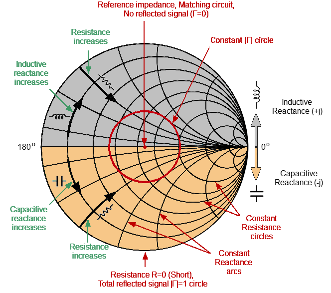
How To Use A Smith Chart
How To Use A Smith Chart - They define how to draw constant resistance circles. Learn smith chart basics, how to read a smith chart and smith chart impedance matching. On this page, we'll start the beginning of impedance matching, by illustrating the effect of a series inductor or a series capacitor on an impedance. What matters is knowing the basics and how to use them, like always. It consists of two sets of circles for. Once impedance matching requirements are determined, the results can be. Follow the latest updates or read through the posts below. The smith chart is a polar plot of the complex reflection coefficient, γ, for a normalized complex load impedance zn = r + jx, where r is the resistance and x the reactance. It outlines the equations that the smith chart is derived from. This brief tutorial explains what the smith chart is and how it can be used to represent complex impedances. Summary the smith chart is a highly useful tool: The smith chart is a key tool in rf engineering and circuit design. It consists of two sets of circles for. It outlines the equations that the smith chart is derived from. This brief tutorial explains what the smith chart is and how it can be used to represent complex impedances. Smith chart is plotted on the complex reflection coefficient plane in two dimensions and is scaled in normalised impedance (the most common), normalised admittance or both,. We will then use the smith chart to perform impedance matching with. The z smith chart and y smith chart serve specific purposes,. Learn smith chart basics, how to read a smith chart and. Complex impedance transformations determining vswr, rl, and much more transmission line impedance. Once impedance matching requirements are determined, the results can be. Follow the latest updates or read through the posts below. The smith chart makes this easy to visualize. We will then use the smith chart to perform impedance matching with. The smith chart contains almost all possible impedances, real or imaginary, within one circle. Learn how a series rlc circuit with arbitrary component values can be represented as a point on the smith chart and how an impedance contour on the smith chart. The representation of circuit elements in the smith chart is discussed in this chapter starting with the. This brief tutorial explains what the smith chart is and how it can be used to represent complex impedances. The smith chart provides a graphical representation of γ that permits the determination of quantities such as the vswr or the terminating impedance of a device under test (dut). Summary the smith chart is a highly useful tool: Our live coverage. The smith chart makes this easy to visualize. Follow the latest updates or read through the posts below. In this tutorial, we will introduce and explain smith charts, and then given an introduction to impedance matching. The following two equations are essential for constructing the smith chart. Determine swr from the smith chart. That is, suppose that we have an impedance zl on the end of. Complex impedance transformations determining vswr, rl, and much more transmission line impedance. It consists of two sets of circles for. Summary the smith chart is a highly useful tool: An indispensible tool for solving transmission line and waveguide problems, the smith chart was invented in 1939 by. According to president trump, “tariff is the most beautiful word in the dictionary.” throughout his presidential campaign, trump promised to use tariffs as a central part of his. Plot complex impedances on a smith chart. We will then use the smith chart to perform impedance matching with. Our live coverage of president donald trump’s sweeping domestic policy bill has ended. Once impedance matching requirements are determined, the results can be. This brief tutorial explains what the smith chart is and how it can be used to represent complex impedances. Instructions on how to use the smith chart for simple calculations such as converting from admittance to impedance. What matters is knowing the basics and how to use them, like always.. Follow the latest updates or read through the posts below. The following two equations are essential for constructing the smith chart. It outlines the equations that the smith chart is derived from. That is, suppose that we have an impedance zl on the end of. Smith chart is plotted on the complex reflection coefficient plane in two dimensions and is.Smith Chart Example For VSWR, Reflection Coefficient And, 49 OFF
How To Read A Smith Chart Bxelg vrogue.co
Learn Stub Tuning With a Smith Chart Technical Articles
Use the smith chart to determine the input impedance navbermo
Basics Of The Smith Chart Intro Impedance Vswr Transmission Lines Images
How to use smith chart bdaability
Smith chart impedance matching maztru
Basics of smith charts and how to use it for impedance matching Artofit
Using smith chart bogast
Smith Chart Explained How To Use A Smith Chart Explanation Smith
Related Post:


